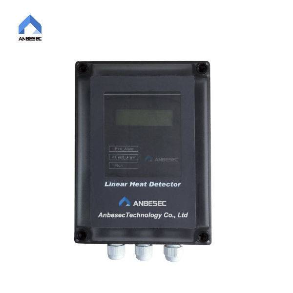
Unità ta' Kontroll NMS1001-L
L-Unità ta' Kontroll NMS1001-L hija apparat ta' kontroll li jimmonitorja l-bidla fit-temperatura tal-kejbil tas-sensur u huwa konness mal-mainframe tal-pannell tal-kontroll tal-allarm tan-nar intelliġenti.
Introduzzjoni
L-NMS1001-L iwettaq monitoraġġ kontinwu tal-allarm tan-nar u ċ-ċirkwit miftuħ taż-żona mmonitorjata kif ukoll id-distanza mill-pożizzjoni tal-allarm tan-nar. Dawn is-sinjali allarmanti jintwerew fuq l-LCD u l-indikaturi tal-NMS1001-L.
Peress li l-allarm tan-nar għandu funzjoni ta' qfil, l-NMS1001-L irid jiġi skonnettjat mill-provvista tal-enerġija u rrisettjat wara l-ALLARM. Filwaqt li l-funzjoni tal-ħsara tista' tirrisettja awtomatikament, dan ifisser li wara li titneħħa l-ħsara, is-sinjal tal-ħsara tal-NMS1001-L jitneħħa awtomatikament.
1. Karatteristiċi
♦ Għatu tal-kaxxa: Magħmul minn plastik b'rendiment għoli ta' reżistenza kimika, reżistenza għat-tixjiħ u reżistenza għall-impatt;
♦ Klassifikazzjoni tal-IP: IP66
♦ Bl-LCD, tista' tintwera informazzjoni allarmanti varja
♦ Id-ditekter għandu kapaċità għolja ta' reżistenza għall-interruzzjoni billi jadotta kejl fin tal-ertjar, test tal-iżolament u teknika ta' reżistenza għall-interruzzjoni tas-softwer. Huwa kapaċi japplika f'postijiet b'interruzzjoni għolja tal-kamp elettromanjetiku.
2.Introduzzjoni tal-Wajers
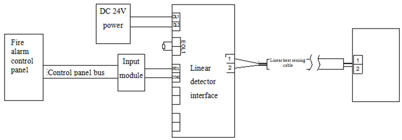
Dijagramma Skematika għat-Terminal tal-Wajers tal-Interfaċċja tad-Detector Lineari:

Fosthom:
(1) DL1 u DL2: qabbdu ma' enerġija DC 24V mingħajr konnessjoni polari.
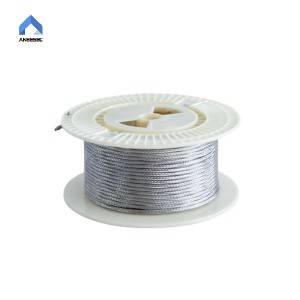
(2)1 2: qabbad mal-kejbil lineari tad-detezzjoni tas-sħana, Il-metodu tal-wajers huwa kif ġej:
| Tikketta tat-terminal | Kejbils tal-kejbil lineari għall-iskoperta tas-sħana |
| 1 | Non-polarità |
| 2 | Non-polarità |
(3) COM1 NO1: output kompost ta' qabel l-allarm/ħsara/normali tal-punt ta' kuntatt tat-terminal
(4) EOL1: punt ta' aċċess 1 tal-impedenza tat-terminal (imqabbel mal-modulu tad-dħul u jikkorrispondi ma' COM1 NO1)
(5) COM2 NO2 NC2: ħruġ ta' ħsara
3. Applikazzjoni u Tħaddim tal-Unità ta' Kontroll u l-Lokatur NMS1001-L
Ixgħel l-Unità ta' Kontroll wara li titlesta l-wajers u l-installazzjoni tas-sistema. L-indikatur aħdar tal-Unità ta' Kontroll jteptep. L-Unità ta' Kontroll tidħol fl-istat ta' inizjalizzazzjoni tal-provvista. Meta l-indikatur aħdar jixgħel kontinwament, l-Unità ta' Kontroll tidħol fl-istat ta' monitoraġġ normali.
(1) Skrin ta' monitoraġġ normali
L-indikatur tal-wiri tal-interfaċċja tad-ditekter lineari taħt tħaddim normali huwa kif ġej fl-iskrin:
NMS1001-L
Teknoloġija Anbesec
(2) Interfaċċja tal-allarm tan-nar
L-indikatur tal-Unità ta' Kontroll taħt allarm tan-nar jidher kif ġej:
Allarm tan-Nar m!
Lokazzjoni: 0540m
L-indikazzjoni “Lokazzjoni: XXXXm” taħt l-istatus tal-allarm tan-nar hija d-distanza mill-post tan-nar sal-Unità ta' Kontroll
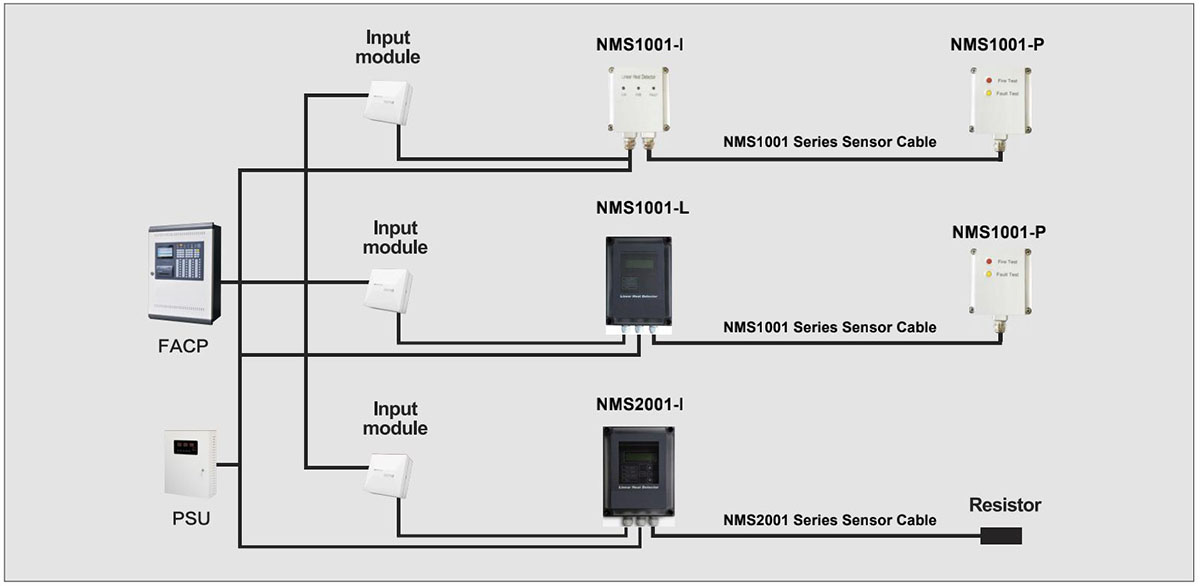
4.Tqabbil u konnessjoni għal NMS1001Sistema -L:
Il-konsumaturi jistgħu jagħżlu tagħmir elettriku ieħor biex jikkonnettjaw ma' NMS1001, u jagħmlu preparazzjoni tajba kif ġej:
Analiżi tal-kapaċità ta' protezzjoni tat-tagħmir (terminal tad-dħul). Waqt it-tħaddim, l-LHD jista' jgħaqqad is-sinjal tal-apparat protett (kejbil tal-enerġija) u jikkawża żieda fil-vultaġġ jew impatt tal-kurrent mat-terminal tad-dħul tat-tagħmir li jikkonnettja.
Analiżi tal-kapaċità anti-EMI tat-tagħmir (terminal tad-dħul). Minħabba l-użu fit-tul tal-LHD waqt it-tħaddim, jista' jkun hemm frekwenza tal-enerġija jew frekwenza tar-radju mill-LHD innifsu li tinterferixxi mas-sinjal.
Dijagramma tal-Konnessjoni tas-Sistema